

When a Small Sensor Causes Big Temperature Problems
Thermostat remote sensor replacement is one of the most overlooked fixes in home comfort — yet a single failing sensor can cause your entire HVAC system to behave erratically.
Here is a quick summary of how to replace a thermostat remote sensor:
- Identify the problem — erratic readings, connection drops, or short-cycling point to a failing sensor
- Find the right replacement — match your thermostat brand, voltage (typically 24V), and sensor type (wired or wireless)
- Cut power — turn off the thermostat or HVAC system before touching any wiring
- Remove the old sensor — unscrew the wall plate and disconnect the wires (or unpair it in the app for wireless models)
- Install the new sensor — connect wires to the correct terminals, mount the wall plate, and seal the wall hole
- Configure the thermostat — update DIP switches, jumper settings, or app settings so the thermostat recognizes the new sensor
- Test it — verify the reading matches the actual room temperature
The problem is common and surprisingly simple to miss. Your thermostat might be working perfectly — but if the remote sensor feeding it temperature data is dead or drifting, your home will still feel too hot in one room and too cold in another. In Birmingham’s humid summers, that imbalance gets uncomfortable fast.
A bad sensor can also cause short-cycling, where your HVAC system turns on and off too frequently, wasting energy and wearing out equipment faster than it should.
This guide walks you through everything — from spotting the signs of sensor failure, to choosing the right replacement, to wiring and configuring it correctly.
Why You Need a Thermostat Remote Sensor Replacement
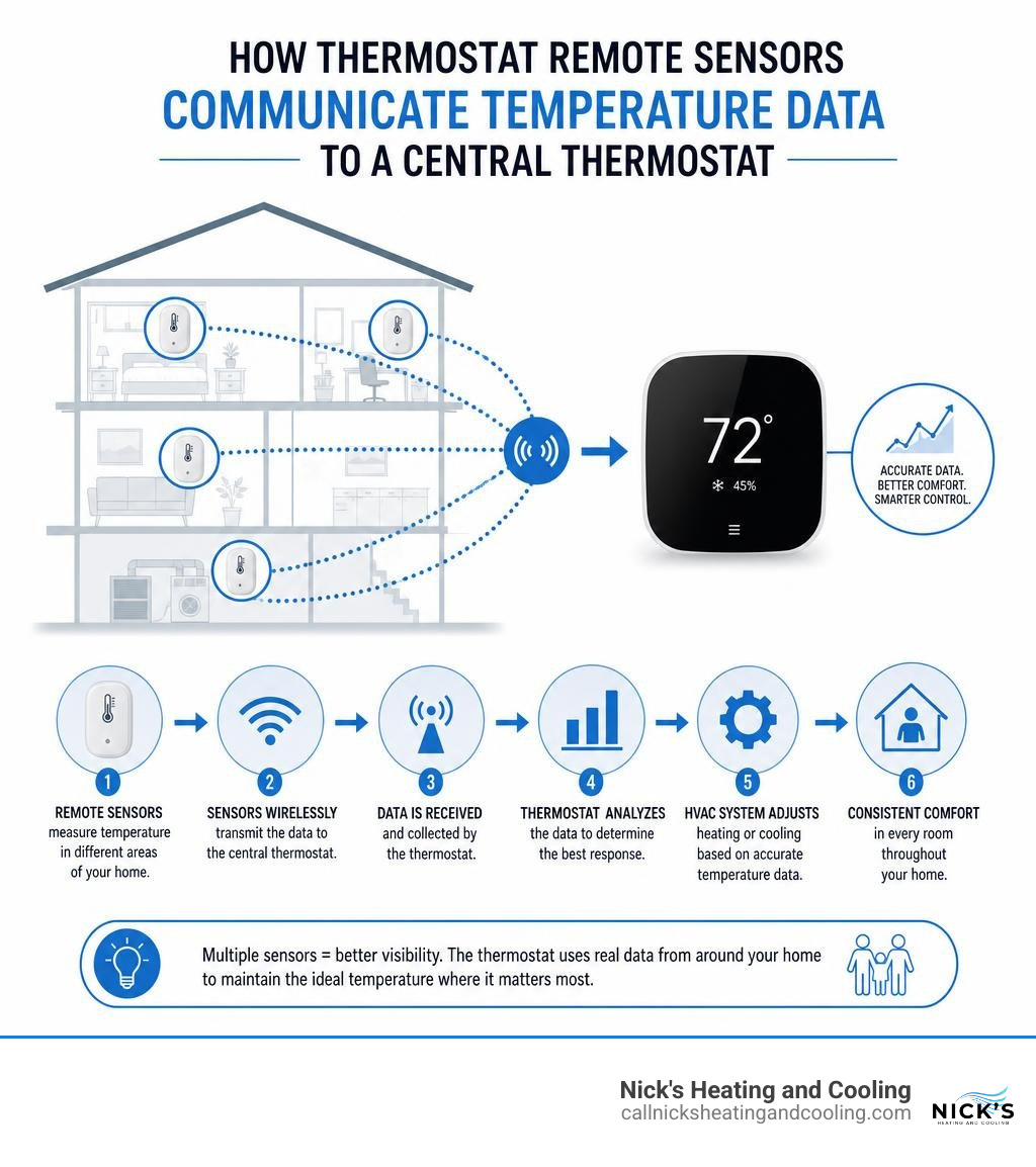
A remote thermostat sensor acts as an extension of your main thermostat’s brain. While the main thermostat unit sits on a wall in your hallway or living room, remote sensors monitor the climate in secondary spaces like upstairs bedrooms, home offices, or drafty basements. If a sensor fails, the brain of your HVAC system receives corrupted or non-existent data, leading to a cascade of performance issues.
There are several primary reasons why a homeowner in the Birmingham or Hoover area might need a thermostat remote sensor replacement:
- Sensor Failure and Degradation: Over time, the internal electronic components of a sensor can degrade. Constant exposure to minor temperature shifts, dust, and humidity can break down the sensitive materials inside the unit.
- Battery Depletion: For wireless sensors, dead batteries are the most frequent culprit. While changing the batteries usually fixes the issue, years of neglecting battery leaks can corrode the internal terminals, ruining the sensor entirely.
- Inaccurate Readings (Temperature Drift): As sensors age, they can suffer from “temperature drift.” This means the sensor thinks the room is 78°F when it is actually 72°F. This forces your air conditioner to run constantly, turning your home into an icebox while driving your utility bills through the roof.
- Short-Cycling: When a sensor sends erratic, rapidly fluctuating readings to the thermostat, the HVAC system may turn on and off in rapid succession. This short-cycling places immense mechanical stress on your compressor and fan motors.
- Physical Damage: Located at “breathing height” on active household walls, remote sensors are highly vulnerable to being bumped by vacuum cleaners, painted over during renovations, or damaged by curious pets and children.
Signs Your System Needs a Thermostat Remote Sensor Replacement
Before you purchase a new sensor, you should confirm that the sensor itself is indeed the problem. Watch out for these classic warning signs:
- Frequent Connection Drops: If your smart thermostat or mobile app constantly alerts you that a specific room sensor is “offline” or “not found,” the sensor’s wireless transmitter is likely failing.
- Erratic Temperature Spikes: If you check your thermostat display and see that an unoccupied guest room is suddenly reporting 110°F or -20°F, the sensor’s internal thermistor has likely shorted out.
- Unresponsive Motion Detection: Many modern smart sensors, such as the Honeywell Home T9, use built-in motion and occupancy detectors to prioritize airflow to occupied spaces. If the sensor fails to recognize when you enter a room, it will fail to adjust the climate accordingly, leaving you uncomfortable.
Selecting the Right Replacement Sensor for Your System
You cannot simply buy any remote sensor off the shelf and expect it to work with your existing thermostat. HVAC control systems rely on specific communication languages and electrical standards.
When preparing for a thermostat remote sensor replacement, you must evaluate the following compatibility factors:
- Brand Compatibility: In almost all residential applications, remote sensors are proprietary. A Honeywell Home thermostat requires a Honeywell sensor, an ecobee requires an ecobee sensor, and a Nest requires a Nest sensor.
- Voltage Requirements: Hardwired remote sensors typically operate on low-voltage AC power, usually ranging between 18V and 30V AC (with 24VAC being the industry standard). Wireless sensors, on the other hand, run on DC battery power (typically requiring AAA alkaline batteries or CR2032 coin cells).
- Communication Protocols: Wireless sensors communicate using radio frequencies (RF) such as Zigbee, Z-Wave, Bluetooth, or proprietary sub-GHz bands. Hardwired sensors use analog resistance signals or digital serial communication to send data back to the thermostat.
Below is a quick reference table comparing typical specifications for common wired and wireless remote sensor types:
| Specification | Wired Remote Sensors | Wireless Smart Sensors |
|---|---|---|
| Power Source | 24VAC (from thermostat) | Batteries (AAA or Lithium Coin) |
| Max Distance | 200 to 300 feet (cable run) | 60 to 100 feet (unobstructed RF) |
| Averaging Capability | Yes (often up to 6 sensors) | Yes (often up to 20 sensors) |
| Additional Features | Manual override buttons | Motion & humidity detection |
| Wiring Required | 2-wire or 3-wire shielded cable | None |
Matching Specifications for Your Thermostat Remote Sensor Replacement
If you are replacing a hardwired analog sensor, you must match the resistance values of the old sensor. Most legacy wired sensors use a Negative Temperature Coefficient (NTC) thermistor. An NTC thermistor’s electrical resistance decreases as the ambient temperature increases.
For example, the popular Honeywell Home C7189U Remote Indoor Sensor features highly specific resistance curves:
- At 40°F (4.4°C), the sensor should measure approximately 22,537 Ohms of resistance.
- At 70°F (21.1°C), the resistance drops to 11,578 Ohms.
- At 100°F (37.8°C), the resistance drops further to 6,301 Ohms.
If you connect a replacement sensor with a different resistance rating (such as a 10k-Ohm Type II vs. a 20k-Ohm thermistor), your thermostat will read the temperature completely incorrectly, potentially displaying a constant error or an extreme temperature value.
For wireless systems, pay close attention to the frequency bands used. If you live in a large home in Hoover, AL, with thick plaster walls or heavy radiant barriers, standard 2.4 GHz Wi-Fi sensors may struggle to maintain a connection. In these environments, choosing a system that operates on a lower, more penetrative sub-GHz frequency band is highly beneficial.
Step-by-Step Guide to Thermostat Remote Sensor Replacement
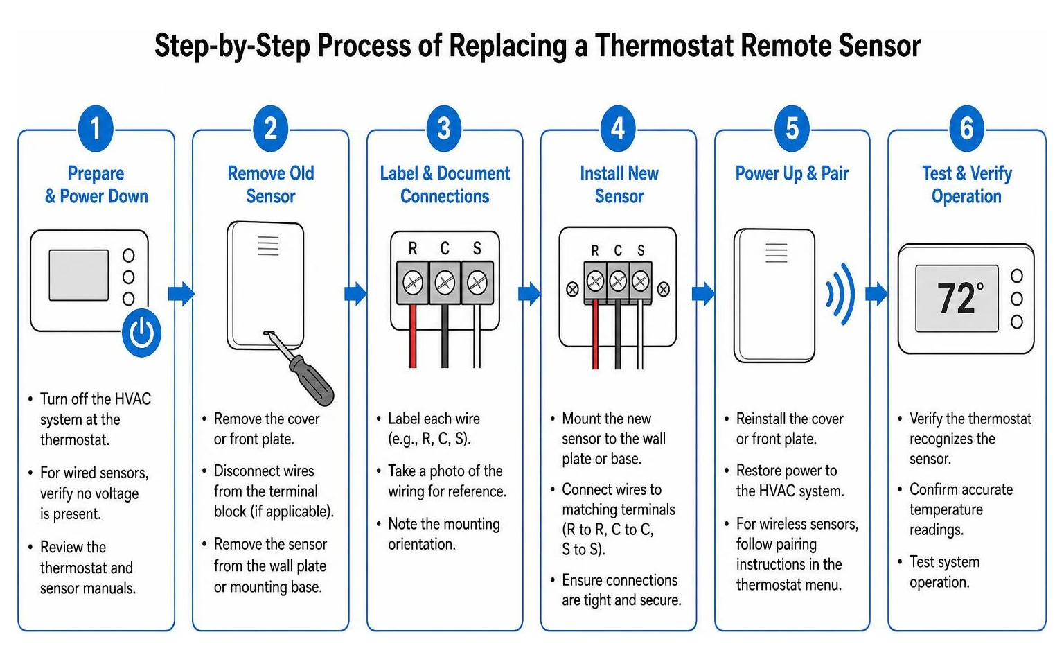
Replacing a thermostat remote sensor is a highly manageable DIY project if you follow the correct sequence and safety protocols. Whether you are dealing with a hardwired legacy sensor or a modern wireless smart sensor, this step-by-step walkthrough will guide you through the process safely.
Tools and Materials Needed:
- Replacement remote sensor (compatible with your thermostat model)
- Precision screwdrivers (flathead and Phillips)
- Wire strippers (for wired sensors)
- Digital multimeter (to test voltage and resistance)
- Non-flammable wall insulation or silicone caulk (to seal wall drafts)
- Drywall anchors and screws (usually included with the new sensor)
- 3/16-inch drill bit and power drill (if mounting a new wall plate)
- Fresh AAA alkaline batteries (for wireless models)
Wiring Configurations for Hardwired Sensors
If you are replacing a hardwired sensor, the wiring configuration is the most critical part of the job. Always begin by disconnecting the power supply at your home’s breaker panel or HVAC power switch. Working on live low-voltage wires can easily short out the delicate transformer on your furnace or air handler control board.
Once the power is safely off, remove the cover of the old sensor to expose the terminal block.
1. The 2-Wire Configuration
Many standard indoor sensors, like the SEN-500-1 Remote Indoor Temp Sensor , utilize a simple 2-wire configuration. These analog sensors have no polarity. This means it does not matter which wire connects to which terminal on the sensor board.
- Step A: Take a clear photo of the existing wiring terminals for reference.
- Step B: Disconnect the two wires from the old sensor terminals.
- Step C: Mount the new sensor wall plate, pulling the wires through the center opening.
- Step D: Strip approximately 1/4-inch of insulation from the wire ends and secure them to the terminals on the new sensor.
- Step E: Pack non-flammable insulation or duct seal compound into the hole in the drywall behind the sensor. This blocks drafty air inside the wall cavity from blowing directly onto the back of the sensor board, which would otherwise skew your temperature readings.
2. The 3-Wire Configuration
More advanced digital remote sensors require a 3-wire connection to power local LED indicators or transmit serial data. These systems use dedicated terminals, typically labeled:
- RS1 (Sensor Data / Return)
- RS2 (Sensor Signal)
- RS+V (24VAC Power Supply)
When replacing a 3-wire sensor, you must match the terminal names on the sensor board exactly to the corresponding terminals on your thermostat backplate. Wire colors can vary widely depending on the technician who originally installed your system, so relying on terminal labels rather than wire colors is a best practice.
Preventing Electrical Interference
To prevent erratic temperature readings and communication failures, never run your low-voltage remote sensor wiring inside the same conduit or wall cavity parallel to high-voltage (120V/240V) home power lines. Keep sensor cables at least one foot away from large inductive loads like electric motors, fluorescent lighting ballasts, and household appliances. If you must cross a high-voltage line, always cross it at a 90-degree angle to minimize electromagnetic interference.
Pairing and Configuring Wireless Sensors
Wireless smart sensors make physical installation incredibly easy, but they require proper software configuration to communicate with your thermostat.
If you are replacing an old, broken wireless sensor, you must first unpair the old unit before the system will allow you to register the replacement.
Step 1: Remove the Old Sensor from the System
Open your smart thermostat’s on-screen menu or companion mobile app (such as the Resideo app for Honeywell systems). Navigate to the “Sensors” or “Accessories” menu, select the failing sensor, and click “Delete,” “Remove,” or “Unpair.”
Step 2: Prepare the New Sensor
Pop open the cover of your new wireless sensor and install fresh, high-quality AAA alkaline batteries. Avoid using rechargeable batteries, as they have a lower nominal voltage (1.2V vs 1.5V) and will cause your sensor to report a low-battery status prematurely.
Step 3: Initiate Pairing Mode
On your thermostat or mobile app, select “Add New Sensor” or “Pair Accessory.” On the physical remote sensor, press and hold the pairing button (often located inside the battery compartment or on the side of the casing) until the LED indicator begins flashing.
Step 4: Configure DIP Switches and Jumpers
Some universal wireless and wired systems, such as those detailed in the NetX™ NT-URS Universal Remote Sensor manual, rely on physical DIP switches and jumper pins to define their role in your home.

Before mounting the sensor, check the circuit board for these settings:
- DIP Switches: These switches tell the sensor whether it should act as an Indoor Sensor, Outdoor Sensor, Humidity Sensor, or Auxiliary Temp Probe. Ensure the switches on your new sensor match the configuration of the old one.
- Sensor Counting Jumpers: If you are connecting multiple sensors to a single thermostat, you must set the jumper pins to match the total number of sensors in the network (e.g., setting the jumper to the “1-2”, “3-5”, or “6+” position). This ensures the thermostat applies the correct mathematical algorithm to average the temperatures across your rooms.
Critical Placement Rules for Accurate Temperature Readings
Even the most advanced, high-end sensor will perform poorly if it is mounted in the wrong location. Whether you are installing a wired or wireless model, follow these critical mounting rules to ensure your system reads the true ambient climate of your living spaces:
- Mount at Breathing Height: Install the remote sensor approximately 5 feet (1.5 meters) above the floor. This is the standard height where air temperatures are most representative of human comfort. Mounting it too high (near the ceiling where hot air rises) or too low (near cold floors) will cause inaccurate HVAC cycling.
- Choose an Inside Partitioning Wall: Always mount sensors on interior walls. Exterior walls are highly influenced by outdoor temperatures, even in well-insulated homes. Keep the sensor at least 18 inches (46 cm) away from any outside walls.
- Avoid Dead-Air Zones: Do not place sensors behind doors, in tight corners, or inside bookshelves. These areas trap air, leading to sluggish sensor response times and inaccurate readings.
- Keep Clear of Direct Drafts: Avoid mounting sensors directly in the path of supply air registers, return air grilles, or drafty exterior doors and windows.
- Shield from Radiant Heat: Keep the sensor away from direct sunlight, fireplaces, television sets, lamps, and kitchen appliances. A lamp sitting directly beneath a sensor can easily raise the local temperature reading by 5°F to 10°F, throwing off your entire home’s climate control.
Frequently Asked Questions about Thermostat Remote Sensors
Can I use a remote sensor to completely replace my physical thermostat?
Technically, yes, but it is highly discouraged as a primary setup. Using a smart relay (like a dry-contact switch) combined with home automation software allows you to run a “virtual thermostat” driven entirely by a remote sensor.
However, this setup lacks critical physical fail-safe mechanisms. If your home Wi-Fi router crashes, your smart hub goes offline, or the sensor battery dies, a virtual thermostat can fail in the “ON” position. In the winter, this could run your furnace continuously, creating a severe fire hazard or overheating your home. In the summer, it could cause your AC compressor to freeze up.
A physical smart thermostat should always remain installed as the primary system controller. It acts as a local processing unit, ensuring that even if the internet goes down, your HVAC system operates safely.
How many remote sensors can I connect to a single thermostat?
The maximum number of sensors depends entirely on your specific thermostat model:
- Modern Smart Thermostats: Systems like the Honeywell Home T9 support up to 20 wireless smart sensors connected to a single thermostat.
- Hardwired Legacy Systems: Many commercial and residential wired thermostats support up to 6 remote sensors wired together for temperature averaging.
- Duct and Specialty Sensors: Systems utilizing specialized duct probes, such as those described in the Thermostat Manual , often allow up to 3 daisy-chained sensors to monitor return and supply air temperatures directly within your HVAC ductwork.
When multiple sensors are connected, you can configure your thermostat to average the readings across all active sensors, or focus exclusively on a single prioritized room (like an active home office during the day and the master bedroom at night).
Why is my new remote sensor displaying an abnormally high temperature?
If your newly installed remote sensor is displaying an incredibly high temperature (such as 99°F or higher in a room that feels like 70°F), it is usually caused by one of three common issues:
- Touching Thermistor Wires: On hardwired analog sensors, the actual temperature-sensing element is a tiny bulb called a thermistor. If the two small, uninsulated metal legs of the thermistor inside the sensor casing are bent and touching each other, it creates a short circuit. This drops the electrical resistance to zero, forcing the thermostat to display an abnormally high temperature. Carefully open the sensor cover and ensure the two thermistor wires are separated.
- Unsealed Wall Cavity Drafts: If the hole in the drywall behind a wired sensor is left open, warm, stagnant air from inside your wall framing can seep into the sensor housing. During hot Alabama summers, wall cavities can become incredibly hot, skewing the sensor’s reading. Always seal the wire entry hole with silicone caulk or non-flammable insulation.
- Incorrect Thermostat Calibration: The thermostat may still be calibrated for the old sensor’s resistance profile. You may need to access the installer setup menu on your thermostat to reset the sensor calibration or manually adjust the temperature offset.
Conclusion
A properly functioning remote thermostat sensor is the secret to eliminating uncomfortable hot and cold spots, protecting your HVAC equipment from short-cycling, and keeping your energy bills under control. Whether you are swapping out a simple wireless room sensor or wiring a complex multi-sensor averaging network, paying close attention to compatibility, wiring safety, and placement rules will ensure your home remains perfectly comfortable year-round.
Because Birmingham’s intense summer heat and high humidity place a heavy load on your heating and cooling equipment, even a minor sensor calibration issue can quickly escalate into high utility bills or system wear and tear.
If you aren’t comfortable handling low-voltage wiring, diagnosing NTC thermistor resistance curves, or configuring advanced thermostat installer menus, we are here to help. The certified, locally-owned team at Nick’s Heating and Cooling is ready to assist. We serve homeowners throughout Birmingham, AL, and Hoover, AL, with professional HVAC diagnostics, system balancing, and thermostat calibration.
Schedule a free, no-obligation inspection with Nick’s Heating and Cooling today, and let our experienced technicians restore perfect, balanced comfort to every room in your home!