

Start Your Hoover Thermostat Installation Safely
A successful Hoover thermostat installation starts with three basics: confirm your HVAC system uses low-voltage 24V controls, turn off power at the breaker, and photograph and label every wire before removing the old thermostat. Then mount the new wall plate level, connect each wire to the matching terminal, restore power, and complete the thermostat’s setup prompts.
Most replacements take 30 to 60 minutes when the new thermostat is compatible with the system. Smart and programmable models can improve comfort with schedules, remote control, and temperature alerts, but they often need a C-wire for steady 24V power.
Do not install a standard home thermostat on 120V or 240V line-voltage equipment, and stop if you find stranded wiring, a proprietary control system, or wiring that does not match the installation guide. Those situations call for an experienced HVAC professional.
In Hoover’s hot, humid summers and changeable heating season, the right thermostat settings and placement can make a real difference in comfort and system performance.
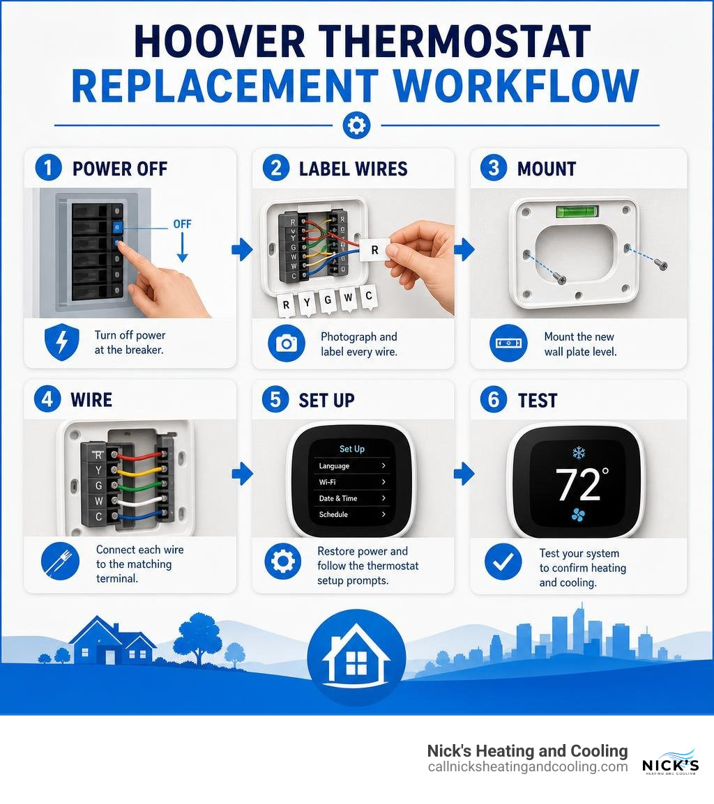
Hoover thermostat installation word guide:
Preparing for Your Hoover Thermostat Installation: Tools and Safety

Before touching a single wire on your wall, proper preparation is key to avoiding a blown control board fuse or an unnecessary service call. A smooth DIY project relies on gathering the right tools, testing for live current, and confirming that your existing system operates on standard residential control voltage.
To complete the installation, you will need:
- Standard precision screwdrivers (flathead and Phillips)
- A non-contact voltage detector or multimeter
- A cordless drill with a 7/32-inch bit for drywall anchors
- A small bubble level (or the built-in level on modern baseplates)
- Wire labels or masking tape with a permanent marker
- Safety glasses
- A smartphone or digital camera to photograph original connections
The most critical safety measure is verifying that your heating and cooling equipment uses low-voltage control circuits rather than line-voltage power. Standard smart and programmable wall thermostats operate strictly on 24VAC (alternating current). Connecting a low-voltage thermostat to line voltage will destroy the device immediately and poses a serious electrical fire hazard.
| System Characteristic | Low-Voltage Systems (Standard Residential) | Line-Voltage Systems (Baseboard / Direct Power) |
|---|---|---|
| Typical Voltage | 24 VAC (control circuit) | 120 VAC or 240 VAC (main power) |
| Wire Gauge & Style | Thin (18-gauge solid copper), multi-conductor | Thick (12-gauge or 14-gauge), heavy stranded or solid |
| Wire Labels | R, C, Y, W, G, O/B | L1, L2, Line, Load |
| Equipment Controlled | Central split systems, heat pumps, gas furnaces | Electric baseboard heaters, radiant ceiling heat |
| Smart Compatibility | Widely compatible with modern smart thermostats | Incompatible with standard 24V smart units |
Always shut off power at both the primary circuit breaker panel and the dedicated furnace or air handler power switch before removing your existing thermostat. Use your non-contact voltage detector across the terminal block to ensure no electrical potential remains active.
Choosing the Right Thermostat for Alabama Weather
Our local climate in Hoover presents unique HVAC demands, shifting from intense, humid summer heat to sudden winter cold snaps. Choosing a control unit that matches your heating and cooling setup ensures year-round comfort and system longevity.
If your home utilizes a traditional gas furnace paired with an air conditioner, standard programmable options allow you to schedule recovery periods so the system cools down before peak afternoon heat. When installing units like the Honeywell RTH7500 series, you benefit from built-in Smart Response technology, which learns how long your equipment takes to reach target temperatures and initiates cycles early.
For electric heat pumps—prevalent throughout Jefferson and Shelby counties—ensure your chosen model supports multi-stage heating and dedicated auxiliary heat configurations. If you are also scheduling a new AC installation, pairing the equipment with a compatible smart thermostat unlocks features like automatic seasonal changeovers and remote humidity control.
Ideal Wall Placement and Sensor Positioning
A thermostat can only regulate temperature based on the air it measures. Poor physical placement causes short-cycling, hot spots, and inflated electric bills.
Follow these placement guidelines:
- Interior Walls Only: Mount the control unit roughly 4 to 5 feet (1.5 meters) above finished floor level on an interior partition wall where interior air circulates freely.
- Avoid Direct Thermal Interference: Keep the thermostat away from direct sunlight through windows, exterior door drafts, bathroom steam vents, and kitchen appliances.
- Keep Clear of Supply Registers: Avoid mounting the unit directly beneath or opposite supply airflow registers, which trick the sensor into shutting off before the rest of the room reaches temperature.
If your central hallway location does not reflect the temperature of bedrooms or living spaces, adding remote wireless sensors balances whole-home comfort. Learn how to maintain these additions with our remote sensor replacement guide.
Step-by-Step Guide to Replacing and Wiring Your Thermostat
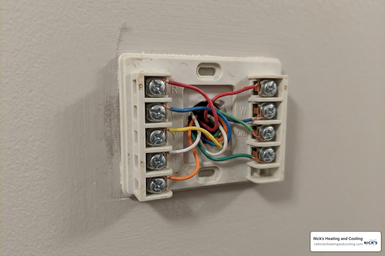
Replacing your wall unit requires careful terminal matching and clean mechanical mounting. Modern units often use universal wall plates (such as Honeywell’s UWP mounting system) that simplify physical installation without requiring loose jumper pins between terminals.
Safe Preparation and DIY Hoover Thermostat Installation Steps
Follow this systematic sequence to complete your project safely:
- Cut All Power: Switch off the dedicated breakers for both the indoor air handler/furnace and the outdoor condenser unit.
- Remove the Old Cover: Unsnap the faceplate of the old unit. If you encounter an older mechanical thermostat containing a glass bulb, handle it carefully without breaking the mercury switch inside.
- Photograph Existing Wires: Take clear photos of every wire securely seated in its original terminal block before loosening screws.
- Apply Wire Labels: Attach the stickers provided in your thermostat box to match each respective terminal letter (R, C, Y, G, W, O/B). Do not label jumper wires connecting R to Rc.
- Secure Loose Wires: Disconnect the wires and wrap them lightly around a pencil to prevent the bundle from slipping backward into the wall cavity.
- Mount the New Baseplate: Route the wire bundle through the center opening of the new wall plate. Level the plate, mark your screw positions, drill holes using a 7/32-inch bit, tap in the drywall anchors, and secure the backplate firmly.
- Seat the Wires: Insert each labeled solid copper wire into its corresponding push-terminal or screw-down block.
If you encounter minor operating glitches after mounting, review our guide on how to fix thermostat issues on a budget for quick adjustments.
Low-Voltage Wiring for Heat Pumps and Conventional Units
Understanding terminal letters ensures your heating and cooling operate in harmony rather than counteracting each other.
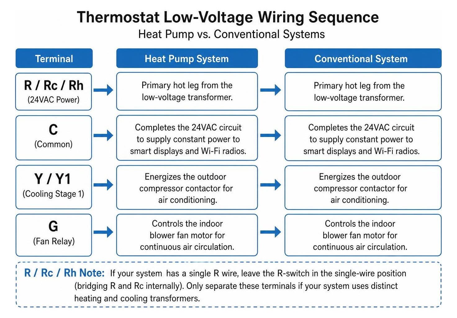
Here is how standard low-voltage terminals function:
- R / Rc / Rh (24VAC Power): The primary hot leg from the low-voltage transformer. If your system has a single R wire, leave the R-switch in the single-wire position (bridging R and Rc internally). Only separate these terminals if your system uses distinct heating and cooling transformers.
- C (Common Wire): Completes the 24VAC circuit to supply constant power to smart displays and Wi-Fi radios.
- Y / Y1 (Cooling Stage 1): Energizes the outdoor compressor contactor for air conditioning.
- G (Fan Relay): Controls the indoor blower fan motor for continuous air circulation.
- W / W1 / AUX (Heating / Auxiliary): Controls the gas valve, electric heat strips, or furnace ignition sequence.
- O/B (Reversing Valve): Dedicated to heat pumps. The setting determines whether the reversing valve energizes in cooling mode (O, common in standard systems) or heating mode (B).
When wiring modern digital controls, refer to specific manufacturer documentation such as the Honeywell T5 Smart Thermostat installation manual or the Honeywell T9 Thermostat guide to ensure the internal switch positions align with your equipment.
Programming and Optimizing Your System for Hoover Climate
Once your new thermostat is securely mounted and powered, programming tailored schedules prevents excess energy consumption while keeping your home comfortable through varying Alabama weather conditions.
Advanced Configuration and System Setup
During the initial digital configuration menu, configure these critical system parameters:
- System Type Selection: Define whether your equipment is a standard gas furnace with AC, an electric air handler, or an air-source heat pump. Mismatches here will cause your outdoor unit to blow cold air when heating is requested.
- Compressor Protection Delay: Ensure the built-in 5-minute minimum-off timer is activated. This prevents the outdoor compressor from restarting immediately after shutting down, protecting internal components from damaging head pressure.
- Reversing Valve Logic: For heat pumps, configure the O/B terminal logic to energize in cooling for most brands.
- Smart Scheduling & Geofencing: Set energy-saving setbacks (e.g., 78°F cooling when away during summer workdays and 72°F during occupied hours). Smart thermostats utilize phone location data to adjust setpoints automatically as you approach home.
To keep your newly controlled equipment operating at peak efficiency, remember to schedule annual air conditioning maintenance before the extreme summer temperatures arrive.
Professional Support for Hoover Thermostat Installation Projects
While standard single-stage replacements are straightforward DIY tasks, complex residential configurations require professional tools and diagnostic instruments. You should contact a technician if you encounter:
- Stranded aluminum or copper wiring that cannot seat securely in push-in terminals
- High-voltage 120V/240V baseboard controls
- Communicating, proprietary HVAC networks that rely on digital data buses rather than 24VAC relays
- Missing C-wires where running a new multi-conductor line through finished walls is necessary
- Complex multi-zone damper control panels
Hiring a certified HVAC contractor guarantees that your electrical connections, control boards, and multi-stage heating systems comply fully with local codes and manufacturer warranties.
Frequently Asked Questions About Thermostat Upgrades
Do I need a dedicated C-wire to install a modern smart thermostat?
Most modern Wi-Fi thermostats require a dedicated common wire (C-wire) to provide an uninterrupted 24VAC power loop for screen backlights and continuous network connectivity. Without a C-wire, some thermostats attempt “power stealing” from heating or cooling circuits, which can cause compressor chattering, short-cycling, or blown control board relays. If your existing wall cable lacks an unused conductor for the C terminal, you can install a power extender adapter at the indoor furnace control board or have a technician pull fresh 18/8 thermostat wire.
How does a residential setup differ from a scientific Nosé–Hoover thermostat?
The term “thermostat” appears in both residential climate control and computational statistical physics, but they are entirely different concepts:
- A residential thermostat is a physical electromechanical or digital device that regulates ambient room temperature by cycling 24V relays connected to furnaces, heat pumps, and air conditioning units.
- A Nosé–Hoover thermostat is a mathematical algorithm used in molecular dynamics simulations to maintain constant temperature (a canonical ensemble) by introducing a computational thermal reservoir or friction variable into the equations of motion.
While both systems aim to control thermal equilibrium, one involves low-voltage household wiring, while the other involves advanced computational physics.
Why is my thermostat display blank after installation?
A blank digital screen usually points to an open electrical circuit:
- Tripped Circuit Breaker: Verify that all HVAC breakers in your main panel are pushed firmly to the “ON” position.
- Door Safety Switch Open: Most furnaces and air handlers feature an interlock switch on the blower compartment door. If the door panel is loose or removed, power to the low-voltage transformer is interrupted.
- Blown Low-Voltage Fuse: If wires touched each other while power was live, the 3A or 5A automotive-style fuse on the indoor furnace circuit board may have blown and will need replacement.
- Improper C-Wire Connection: Ensure the C-wire is securely locked into both the wall plate terminal and the furnace control board.
Conclusion: Achieving Reliable Home Comfort
A properly completed thermostat upgrade transforms your indoor environment, lowering monthly power bills and protecting your HVAC equipment from unnecessary strain. Whether you are adding a basic programmable unit or integrating an advanced smart home system, taking time to handle low-voltage connections carefully pays dividends in efficiency.
If you run into missing wires, complex heat pump setups, or simply want total peace of mind, turn to a trusted Hoover HVAC contractor like Nick’s Heating and Cooling. Our certified, locally-owned technicians provide free, no-obligation inspections across the greater Birmingham area, delivering prompt, professional service tailored to your home’s needs.
Nick’s Heating and Cooling currently services Birmingham, Hoover, Vestavia Hills, Mountain Brook, Alabaster, Chelsea, Homewood, Trussville, Pelham, and Irondale for all your HVAC and Heating needs.